   |
|||||||||
LANGUAGE   |
|||||||||
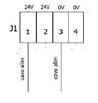
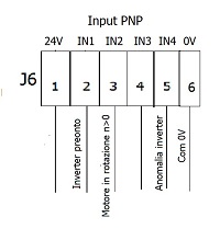
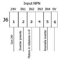
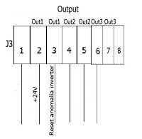
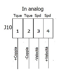
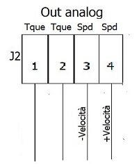
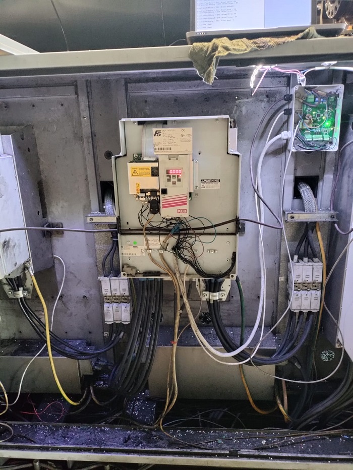
INVERTER.......................................................Requirements for the inverter on Sandretto machin .........................................................................Anological-Digital inverter signals Place the new Inverter in the electrical cabinet of the machine, taking care to connect any cooling hoses, checking for leaks. Connection the 400 Volt input power supply, respecting the phase sequence motor cables, and braking resistor cables. Make Encoder connection between motor and Inverter Place the converter board next to the inverter in the electrical cabinet of the machine, and make the electrical connections between inverter and converter board. Connect the signals of: motor not active inverter enable inverter rotation consent fast stop external fault (signals already present to be identified on new inverter terminal board and connected according to machine wiring diagram) Convert board can-analogico CanBus: terminal J4 (cable present on the old inverter) Pin 1 = can L (cable can in) Pin 2 = can L (vable can out) Pin 3 = gnd (cable can in) Pin 4 = can H (cable can in) Pin 5 = can H (cable can in) 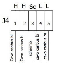 |
|||||||||